This tutorial of Robo India explains how to drive Stepper Motor Using ULN2803 with Arduino UNO.
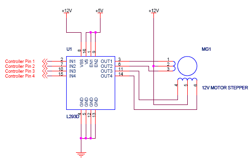
- Uln2803 Stepper Motor Driver Circuit Diagram
- Uln2803 Stepper Motor Driver Circuit Board
- Uln2803 Stepper Motor Driver Circuit
1. Introduction
Stepper motors are like DC motors, which is used to move in steps. These motors have multiple coils that are organised in group which is known as phase. In this tutorial, we have explained how to interface Step Motor 28BYJ-48 with Arduino UNO using ULN2803.
Stepper motors fall somewhere in between a regular DC motor and a servo motor. Servo motors are usually limited to 0-180 degree rotation, while a stepper motor can rotate continously like dc motors. They have the advantage that they can be positioned accurately and you can control over the movement. The only drawback of step motor is, they are little bit harder to control than other motors and servo motors.
1.1 Stepper Motor Working:
There are two types of Stepper motors: Unipolar and Bipolar. The difference between the two types is the voltage levels.
A unipolar stepper motor only operates with positive voltage, so the high and low voltages applied to the electromagnetic coils would be something like 5V and 0V.
Allegro A3967 a low-power dual bipolar stepper motor with a circuit power of 400mA 700mA operating voltage 4.5v to 20V. Allegro A3986 motor drive circuit is a dual full-bridge motor driver with integrated micro-stepping converter suitable for driving high-powered industrial bipolar 2-phase stepping motors (typically 30 to 500W). Unlike earlier drivers, the data sheet for this driver even suggests using it for motor control applicatons, with supply voltages up to 18 volts and up to 250 milliamps per motor winding. One of the problems with commercially available stepping motor control chips is that many of them have relatively short market lifetimes.
And a bipolar stepper motor has two polarities, positive and negative, so its high and low voltages would be something like 2.5V and -2.5V.
Four relays are connected with four different relays. Check the following link to know more about the practical use of relay driver circuit: Intelligent green house control system. Stepper motor interfacing using Uln2003. While interfacing stepper motor with microcontrollers, relay driver circuit using uln2003 is also used. Having a logical low value, should the power driver circuit be constructed. Motor connections & Drive signals from Datasheet FIGURE 4. Four GPIO signals, monitored at the development kit pins, connected to stepper motor through SDK-51 stepper motor driver circuit. To determine if the ULN2803 is suitable, you need to look at the ULN2803 datasheet to see what its ratings are. Its recommended maximum output current is 350 mA, with an absolute maximum of 500 mA, so the ULN2803 is unsuitable. You will probably need to use separate power transistors to drive your stepper motor.
Different types of Stepper Motors have different numbers of wires like 4,5,6,8. In bipolar stepper motors, there are arrangements of 4 wires. Central wire is not available
The stepper motor, which we have used has 5 wires, implying that it is to be run as a unipolar stepper motor. This 5th wire is to allow current on coils to flow in two directions
1.2 ULN2803 IC:
ULN2803 is a high current, high voltage IC, used to drive high power loads upto 500mA/50V such as relays, motors etc.
2. Hardware required
| S.No. | Item | Quantity |
| 1 | Arduino UNO | 1 |
| 2 | Breadboard | 1 |
| 3 | 28BYJ-48 Stepper Motor | 2 |
| 4 | ULN2803 IC | 7 |
| 5 | Male to male Jumper | 11 |
3. Connection:
Use the colors of the leads to identify them, not the position from which they emerge from the motor.

4. Programming:
5. Output
After uploading the above code, the stepper motor will start rotating continously.
Uln2803 Stepper Motor Driver Circuit Diagram
There are many usage of stepper motors, which includes medical scanners, 3D printers, in cameras, auomated blinds and more.
Uln2803 Stepper Motor Driver Circuit Board
If you have any query please write us at support@roboindia.com
Uln2803 Stepper Motor Driver Circuit
Thanks and Regards
Content Development Team
Robo India
https://roboindia.com